USB-C has changed the way we connect devices. You can charge your smartphone on it, and you can power a 16-inch laptop on it. Why is USB-C so flexible, then? The trick is the advanced pin layout.
The most notable one is that USB-C can supply up to 240 watts of power- that is enough to charge even the power-hungry gaming laptops and other peripheral devices. However, the same connector is also very suitable in a basic mouse or keyboard drawing with only milliwatts, allowing for efficient power flow.
This extensive reference deconstructs the USB-C pin layout to understand how the 24 small pins combine to form the most versatile connector in history.
What Makes USB-C Different from Other Connectors
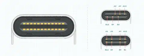
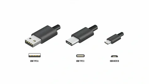
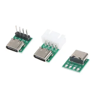
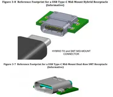
As opposed to older types of USB, the USB Type-C connector is symmetrical and uses 24 pins in two rows. This design allows power to flow in and out, data to be exchanged at high speed, and to produce video in a single port.
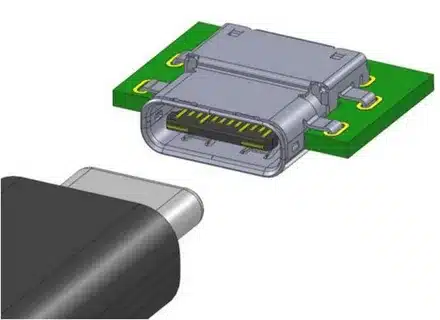
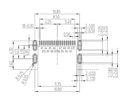
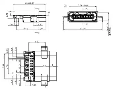
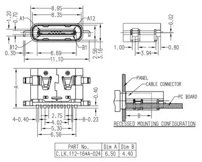
The connector is only 8.4mm by 2.6mm, which is small enough to fit in thin laptops, but strong enough to be used in factories. This makes the USB Type-C receptacle’s reversible design more convenient since there is no problem of guessing how to insert the cables.
The old type of USB connectors used various ports to serve different functions. USB-C simplifies and eliminates all the complexity of the previous generation, but improves the potential.
Understanding the USB-C Physical Layout

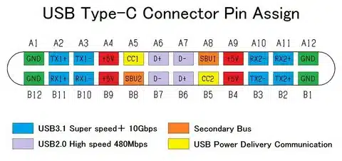
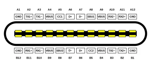
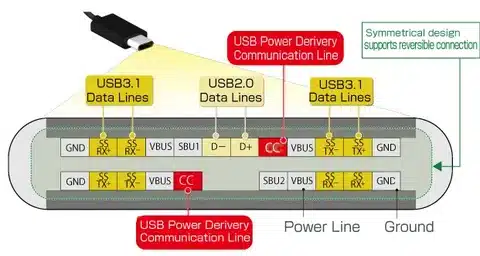
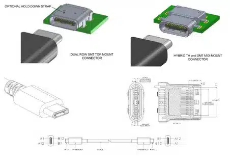
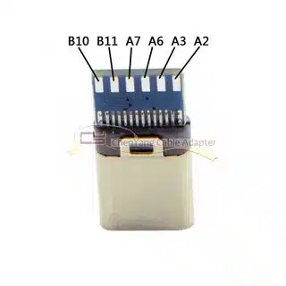
USB-C is numbered A1 through A12 on the top row and B1 through B12 on the bottom row, with the channel configuration pins playing a crucial role. This dual row design makes the USB-C receptacle usable in both orientations as a result of smart pin-mirroring.
The symmetric design implies that pins A1 and B12 are used in the same way, pins A2 and B11 are used in the same way, etc. The duplication has removed the issue of orientation, and it offers strong electrical connections.
The width of each pin is only 0.5mm, and the distance between pins is also 0.5mm, so manufacturing tolerances are very tight. This miniaturization provides the small form factor with signal integrity and power processing abilities.
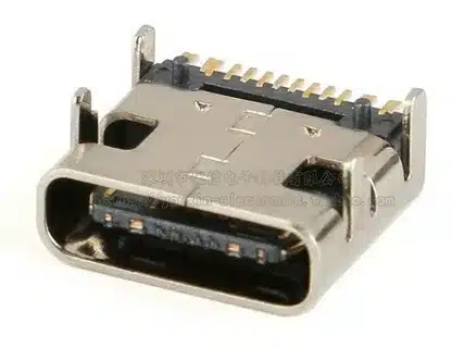
The connector shell offers electromagnetic shielding and mechanical protection, and is reliable when used in harsh environments (consumer electronics and industrial).
Complete USB-C Pin Assignment Overview

Here’s the complete pin assignment for USB-C connectors according to the latest USB specification :
Top Row (A1-A12):
- A1: GND (Ground)
- A2: TX1+ (SuperSpeed differential pair)
- A3: TX1- (SuperSpeed differential pair)
- A4: VBUS (Power)
- A5: CC1 (Configuration Channel)
- A6: D+ (USB 2.0 differential pair)
- A7: D- (USB 2.0 differential pair)
- A8: SBU1 (Sideband Use)
- A9: VBUS (Power)
- A10: RX2- (SuperSpeed differential pair)
- A11: RX2+ (SuperSpeed differential pair)
- A12: GND (Ground)
Bottom Row (B1-B12): includes the downstream-facing port.
- B1: GND (Ground)
- B2: RX1+ (SuperSpeed differential pair)
- B3: RX1- (SuperSpeed differential pair)
- B4: VBUS (Power)
- B5: CC2 (Configuration Channel)
- B6: D+ (USB 2.0 differential pair)
- B7: D- (USB 2.0 differential pair)
- B8: SBU2 (Sideband Use)
- B9: VBUS (Power)
- B10: TX2- (SuperSpeed differential pair)
- B11: TX2+ (SuperSpeed differential pair)
- B12: GND (Ground)
This design offers redundancy to essential functions, as well as allowing the reversible attribute of the connector. Each functional group will play a certain role in power delivery, data transmission, as well as configuration management.
Power Pins: VBUS and Ground Configuration
USB-C connectors use 4 VBUS pins (A4, A9, B4, B9). This redundancy reduces the resistance and allows for higher current to pass through without harm. The distributed power pins allow too much heating and voltage drop at high current conditions.
The default VBUS is 5 V, although Power Delivery negotiation may raise this to 9 V, 15 V, or 20 V according to the needs of devices. The specification of the Extended Power Range now accepts up to 48V 240 W.
Power and signal integrity return paths are on four ground pins (A1, A12, B1, B12). Electromagnetic compatibility and safety are dependent on proper grounding. Multiple ground connections reduce impedance and improve signal quality
USB-C with no Power Delivery, up to 15W (5V, 3A). PD negotiation uses a maximum of 45W on ultrabooks and 60W on standard laptops, 100W on gaming laptops, and 240W with Extended Power Range implementations.
The power delivery system comprises various safety measures, such as overvoltage protection, overcurrent protection, temperature, and cable ability verification functions, to avoid harm and ensure safe operation.
Configuration Channel (CC) Pins Explained
Configuration Channel pins (A5 and B5) are used to perform several important tasks, such as cable orientation detection, device role negotiation, power delivery negotiation, and alternate mode detection.
You insert a USB-C cable, and the device looks at which pin of the CC connector has the pullup resistor. This sets cable orientation and switches on the right data lanes. The CC pins also communicate cable capabilities and device needs with other resistor values.
CC pins relay digital messages between devices to discuss the best possible charging terms. This eliminates any chance of damage by incompatible power levels and also optimizes its performance. The protocol involves the exchange of capabilities, negotiation of contracts, and monitoring.
USB Power Delivery communication, alternate mode negotiation, and cable electronic marking detection are also performed by the Configuration Channel. This complex signal allows the plug-and-play behavior desired by the USB-C users.
The CC protocol includes error detection and recovery mechanisms that make the protocol behave reliably even in difficult electrical environments. The system is able to recover and identify communication errors, cable disconnects, and power delivery failures.
USB 2.0 Data Pins: D+ and D-
USB-C can be retrofitted onto dedicated USB 2.0 pins (A6/A7 and B6/B7). These pins are backward-compatible with older connectors and protocols, so you can use your USB-C connectors with older equipment.
USB 2.0 connections allow a maximum of 480 Mbps. They are slow compared to SuperSpeed lanes but can support keyboards, mice, and simple accessories. To save on expenditures and complexity, many devices are made with USB 2.0 pins only.
Unlike SuperSpeed lanes, which trigger when negotiating, USB 2.0 pins are activated, and therefore, a device is automatically recognized. This makes it easy to enumerate quickly and do simple communications before more powerful options are enabled.
Noise immunity and reliable data transmission are achieved by differential signaling of D+ and D- pins. The pins are also used for recognition of the devices and initial communication during the enumeration process in USB.
USB 2.0 compatibility means that with correct cables and adapters, billions of existing USB devices still work with the USB Type-C port and safeguard user investments, allowing easy migration to newer technologies.
SuperSpeed Data Lanes Deep Dive
SuperSpeed communication consists of four differential pairs: TX1+/TX1- (A2/A3) and RX1+/RX1- (B2/B3) and TX2+/TX2- (B10/B11) and RX2+/RX2- (A10/A11). This setup offers two-way high-speed communication.
The RX (receive) and TX (transmit) designation is based on cable orientation. The intelligent design of USB-C detects the correct direction to set the data flow automatically when CC pin negotiation is in place, making sure that no matter how you connect the cable, you will communicate correctly.
SuperSpeed lanes are capable of supporting a wide range of data rates: USB 3.2 Gen 1 at 5 Gbps, USB 3.2 Gen 2 at 10 Gbps, and USB4 up to 40 Gbps, with some implementations reaching 80 Gbps. These speeds can be used to transfer applications stored on external storage to high-resolution displays.
SuperSpeed lanes are based on the differential signaling that offers excellent noise immunity and signal integrity over cable lengths as long as 3 meters when using passive cables. Signal boosters can be attached to active cables and can be extended over these distances without loss of performance.
USB4 Lane bonding enables several SuperSpeed pairs to be used together, increasing bandwidth to support bandwidth-intensive applications. This method allows the maximum performance rates and, at the same time, is compatible with slower devices.
Sideband Use (SBU) Pins
Sideband Use pins (A8 and B8) are also used for other modes like DisplayPort, which allows video display using USB-C pins. The pins allow customized connectivity to non-standard protocols on top of the standard USB connection.
The signals that SBU pins can carry can be determined by the mode of alternate operation is active: DisplayPort auxiliary channel, audio signals, debug interfaces, or custom protocols. Such adaptability adds to the versatility of USB-C.
SBU pins are used to detect hot plugs to allow displays to remain connected to a monitor and are designed to detect when a cable is connected or disconnected. The pins also deal with the EDID communication that is used to detect display capability.
Alternate mode negotiation: Alternate mode negotiation is a protocol that utilizes the SBU pins alongside CC pins to define compatible operating modes between connected devices. This not only allows maximum performance, but it also avoids incompatible configurations.
Some implementations may also operate analog audio output on the SBU pins and may even substitute traditional headphone jacks with suitable adapters or dongles.
USB-C Power Delivery Protocol
The latest USB-C standard can support power up to 240 watts with voltages as high as 48 V, supporting desktop replacement monitors and laptops. This Extended Power Range needs special cables and devices.
Power Delivery contains various safety features: overvoltage protection, overcurrent detection, temperature control, and cable capability verification. These properties eliminate damage and have the highest efficiency in charging.
Negotiation is a process that entails the initial contact at 5V, exchange of capabilities between the devices, negotiating the contract at the most appropriate power levels and performance, and performance monitoring.
Smart charging algorithms maximize the length of battery life by changing voltage and current according to battery condition, temperature, and charging history. This not only increases battery life but also reduces charging time.
Data Transfer Speed Breakdown
USB 2.0 has a theoretical maximum of 480 Mbps, and in practice, 35-40 MB/s file transfers. This is fast enough to support simple peripherals and most consumer electronics.
USB 3.0 offers 5 Gbps (about 500 MB/s) and USB 3.1 offers 10 Gbps (about 1 GB/s). These speeds allow external storage, video capture, and professional applications.
USB4 specification supports up to 40 Gbps, the same as Thunderbolt 3. In other implementations, this is pushed to 80 Gbps by the use of advanced encoding and multi-lane encoding.
Real speeds are a factor of a number of things: cable quality and length, device capabilities, file system throttling, thermal throttling, and electromagnetic interference. Performance in the real world is usually at least half of the theoretical maximums.
Effective throughput is diminished by protocol overhead, error repair, and flow control. These limits are useful to provide realistic expectations on the data transfer performance associated with various applications.
Alternate Mode Capabilities
DisplayPort Alt Mode reuses the SuperSpeed lanes to transmit video signals, including 8K at 60Hz. This allows USB-C to drive monitors without a video out.
The integration of Thunderbolt 3/4 consists of USB-C connectors but has some added features, such as tunneling of PCIe and daisy-chaining multiple devices. Thunderbolt is a high-performance professional port.
In certain USB-C designs, audio analog mode provides analog audio output, instead of a traditional headphone jack. This needs special hardware support and the right adapters.
Custom alternate modes allow manufacturers to create custom applications such as automotive diagnostics, industrial control, or proprietary high-speed interfaces and still use USB-C.
The alternate mode framework provides negotiated fallback and structured negotiation, so that devices can operate if the preferred modes are not available. This provides for easy use of USB and enables advanced functionality.
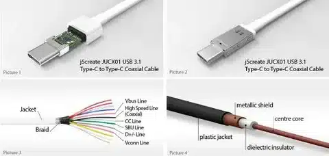
Cable Types and E-Marking
USB-C Standard USB-C cables can carry up to 3A of current and USB 2.0 of data. These simple cables are compatible with most smartphones and accessories and are also low in cost.
E-marked cables with current over 3A carry a chip that transmits cable information to devices that connect to them. This eliminates overloading of cables that are not intended to be used in high-current applications.
Full-featured cables carry 5A current (100W power), USB 3.2, 570Mbps (DisplayPort alternate mode), and other high-speed data. These are the most expensive cables, and they offer the highest functionality.
The length of a cable influences the performance: USB 2.0 cables are usable up to a distance of 5 meters, SuperSpeed cables up to 3 meters, and active cables with signal boosters permit even greater distances.
With proper shielding, twisted pair construction, and the right materials, a quality cable will provide the integrity of the signal and safety. Low-cost cables can lead to a problem in performance or safety.
Device Role Detection and Switching
CC pins define which device will be the host (pushes supply) and which one will be the device (pulls supply and data). Automatic negotiation removes manual switches and setup.
The modern devices usually have the Dual Role Port (DRP) functionality, which automatically changes the mode to use host or device mode. This allows the flexibility of connectivity between laptops, phones, and peripherals.
USB-C enables dynamic role switching, and devices may switch power and data roles without re-cabling. A laptop may power a phone and then be recharged by a dock at some point.
Role detection is a method of communicating the capabilities and preferences of devices by using pull-up and pull-down resistors on CC pins. The negotiation protocol provides compatibility of its operation and avoids conflicts usb Type-C cable high-speed data transfer.
The power role and the data role may be independent, and complex cases, such as a laptop delivering data services, can occur even with longer cable lengths host device.
Common USB-C Pin Issues and Troubleshooting
Pin damage may lead to intermittent connection of power, failure in the delivery of power, failure to transfer data, or total failure of connection. Most problems with the pin can be avoided by careful handling of the USB connector.
Pin contacts are sensitive to moisture and debris. Wipe off with clean isopropyl alcohol and use compressed air to remove debris. Do not be tempted to make a connection in the presence of contamination, custom USB cables.
The construction of poor cables causes voltage drop under load, signal integrity issues, unreliable performance, and safety issues. These problems are mitigated by quality cables made by reputable manufacturers USB Implementers Forum.
Bent pins need connecting or replacing the connector. Trying to straighten pins further damages them and is likely to be unsafe for devices connected.
Inconsistent connectivity can be a sign of damaged connectors or loose cables, or dirt. Testing with known-good cables can be done in a systematic way to isolate problems to individual components, previous USB connectors.
Power Delivery Negotiation Process
Communicating devices – When connecting devices, the CC pins set cable orientation, default 5V power on, devices negotiate capability messages, set the ideal power level, and higher voltage/current on, where supported USB Type-C specification.
Power Delivery features a safe and efficient negotiation of power contracts using a packet-based communication over CC pins. The protocol has error detection and recovery for the USB Type-C plug.
If PD negotiation fails, the devices return to safe default settings, preventing damage and still allowing for a simple operation. This is a reliable way to ensure that it operates on a USB-C connection.
The negotiation process can proceed at the working stage, which provides the opportunity to dynamically adjust the level of power distribution in accordance with the requirements of the device and thermal conditions. This maximises the safety and efficiency of USB standards.
More complex PD functions are programmable power supply operation, rapid role changing, and extended power range operation to support specialized uses where maximum flexibility is needed, USB-C plug.
Future USB-C Developments
USB4 Version 2.0 increases bandwidth to 80 Gbps, whilst being backwards compatible with other devices. This development allows new applications that need very high bandwidth.
It is still in research of wireless implementations that would not require physical connectors, but would still use USB-C protocols. Radiofrequency transmission of power and data might transform the connectivity of devices audio adapter.
Power delivery specifications can also be improved beyond 240 W in specialised applications such as high-end workstations, servers, and in industrial equipment that needs to transfer as much power as it can upstream-facing port.
USB-C is constantly evolving and expanding its capabilities while maintaining compatibility with new standards like PCIe 5.0, DisplayPort 2.0, and better charging capabilities.
Better cable technology, such as optical fibers, materials, and smart cables with processing built into them, could support longer and higher performance.
Practical Applications in Different Industries
USB-C is becoming a common port among consumer electronics, which has helped reduce cable clutter and simplify usage. Smartphones, tablets, and laptops are enjoying standardization.
The automotive and industrial sectors make use of the strength of USB-C and its power delivery capabilities to provide a reliable connection in harsh conditions, default VBUS voltage. The connector is hardy.
USB-C standardization of medical devices allows the use of compatible equipment and less complex inventories. Standardization enhances care of patients due to increased integration of equipment, older USB connectors.
Digital interfaces, power delivery, and control signals on professional audio/video equipment use USB-C. The power and high bandwidth are appropriate during professional demanding applications, USB Type-C functionalities.
The simplicity and universality of USB-C and USB cables will support education technology in reducing the need for technical support while increasing the compatibility of technology with a wide range of educational environments, VBUS, and GND pins.
Choosing the Right USB-C Cables
Consider the maximum power requirements, data transfer, display output requirements, and the limit on the cable length when selecting cables. Optimization of performance is parallel to the adaptation of cable capabilities to the needs of the device.
Identify USB-IF, E-Mark chip on high current cables, proper shielding and construction, and relied-upon manufacturer specifications. Good cables are determined by the use of good-quality indicators.
To avoid breaking devices by using counterfeit products, buy the product from official dealers. Do not forget to confirm whether the product is USB-IF certified, whether the E-Mark is operating properly, and lastly, confirm using known good products.
Cable management issues include cable length, cable flexibility, cable durability, and environmental factors, including temperature and moisture.
The budget should have the capacity to balance the cost and performance requirements. Simple cables are used in most of the applications; those with top capability are the premium cables.
Environmental and Regulatory Considerations
USB-C standardization has led to a reduction in the amount of electronic waste and the ability to reuse cables between devices because all of them use the same connector. This is a green benefit that is finding its way into industries.
Governments worldwide are pushing the adoption of USB-C as the standard charging device, and the concept is extending to any type of device. Under regulatory pressure, proprietary connectors are being phased out.
The benefits of sustainability include a decrease in the complexity of the manufacturing process, the minimization of waste during the packaging process, and an increase in the useful life of the cable. Universal connectors are used to provide the principles of the circular economy.
Material recovery, the right disposal strategy, and recyclability design are part of an end-of-life approach. The uniformity of USB-C assists in fostering the recycling and reusing of materials.
Conclusion: USB-C Pin Layout Mastery
The 24-pin version of USB-C is the ultimate connector design, with the ability to deliver power, transfer data with high velocity, and provide video output in a single reversible connector. The knowledge of this layout makes superior choices of technology.
The four power pins allow safe delivery of high currents, and the SuperSpeed lanes offer blazing data transfer speeds. Configuration Channel pins coordinate complicated negotiations that enable it all to work smoothly.
This knowledge is becoming more and more valuable as USB-C becomes universal. Be it troubleshooting connection problems or developing new products, a knowledge of how these 24 pins interact can be the key to success.
USB-C is the future, and now you see the reason why. USB-C pin layout offers the flexibility that our interconnected world requires, be it smartphones, laptops, displays, or industrial equipment.
Willing to apply this knowledge? Begin auditing your existing cables – make sure you have the correct specifications to match the ability of your devices. Share this manual with other people who may need to learn more about USB-C.