Have you ever wondered what you find in that USB cable that you use daily, including the USB port? You might have to assemble your own project, troubleshoot a charging issue, or simply care about the appearance of the wires of your technology accessories when opened, but knowing how to assemble a USB cable is actually way easier than it might sound. The truth is not so clear, and the majority of people believe that all USB cables are identical. The wires available will also depend on the type of USB that you are dealing with and what your wires are intended to do, which directly impacts what you can and cannot do with the various wires in a USB hub.
Why Understanding USB Wiring Matters
The inside organization of your cable is helpful in the following real-world scenarios: Finding out why a cable is only charging but not transferring data. Designing individual LED cables or self-charge station length power cables. Determining the charging issues of specific equipment. Familiarity with compatibility between different USB standards, including how a hub controller interacts with them. This manual deals with power-oriented changes and awareness related to the USB-C connector to make things simpler and more certain to practice b plug in.
Knowledge of USB wiring is also used in troubleshooting compatibility problems of some devices, developing specific solutions to a given application, and making better choices according to the USB specification when buying cables for various applications. This knowledge is invaluable regardless of whether you happen to be an electronics enthusiast, a repair technician, or just a person wishing to gain a better understanding of their electronic devices and technology positive wire.
The Evolution of USB Standards
Since its release in 1996, The Universal Serial Bus (USB), often referred to as the universal serial bus, standard has grown considerably. Since USB 1.0 was introduced with only a 1.5 Mbps data transfer rate, we have gone through many generations to the present USB4 (40 Gbps), which is approximately 40 times faster than USB 1.0. The evolution of each has also introduced modifications into not only speed but into power delivery capabilities and wire configurations that a USB host can manage
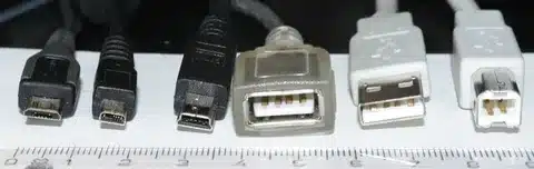
It has also seen the introduction of new types of connectors, such as the Mini-USB, micro B connector, Micro-U, SB, and reversible USB-C, which are smaller in size than the original USB-A and USB-B connectors. Every type of connector performs different tasks and has different wiring needs that influence its functionality and compatibility with computer peripherals.
Understanding Power vs Data Requirements
USB applications do not all need the same degree of functionality. It can be either that some devices simply need power delivery or that some need high-speed data transmission capabilities. This is the basic difference that determines the number and structure of wires in various types of cables, especially in those used for mobile equipment. With only two wires, including the ground wire, power-only applications can be used, but higher-speed data transfer can demand up to 24 wires in advanced USB-C implementations.
Cable quality also varies with the differences between power requirements and data requirements, where data cables must have an exact impedance matching and shielding to ensure signal integrity. These requirements will ensure the appropriate cable is chosen to meet particular applications and devices connected, such as the correct positive voltage wire for power requirements, preventing typical compatibility problems.
Safety First: Important Precautions
The danger is in getting down to the ins and outs of USB cables, especially when handling the negative wire.
Key Safety Hazards:
- Wrong handling of wires is causing short-circuiting.
- Inverse polarity damage to the device.
- Poor insulation risk of fire
- Exposed wire electrocution
- Electronics are broken by voltage spikes.
- Generation of heat by improper connection.
WARNING: You should cease at this point unless you possess the following items: Wire strippers, a Multimeter to measure voltages, Heat-shrink tubing, the correct insulation material, and Basic electrical safety knowledge. By no means change anything without proper tools and precautions, especially when working with an external power supply.
Essential Safety Equipment
In addition to simple tools, good safety equipment is essential to any USB wiring project. These would include safety glasses to guard against pieces of wire, anti-static wrist straps when handling delicate electronics, and maintaining proper ventilation when utilizing soldering equipment. An electrical fire extinguisher is also important to have in the area whenever performing any electrical changes involving a power supply.
Think about working on a good electronics workbench with good lighting and enough room to lay down tools and materials. Mistakes due to poor working conditions when dealing with a standard USB cable may cause safety hazards or a broken piece of equipment.
Materials and Tools You’ll Need

Essential Materials:
- USB cable (appropriate type)
- Heat shrink tube (sizes are different)
- Electrical tape
- Solder (where permanent connections were required)
- Flux for improved soldering
- Cleaning with isopropyl alcohol.
- Cable ties for organization
Required Tools:
- Wire cutters/strippers
- Multimeter (very recommended)
- Soldering iron (if soldering)
- Shrink tube heater or lighter.
- Desoldering braid or pump
- Microscope or magnifying glass.
- Third-hand tool or PCB holder
An effective set of tools will transform a safe and trustworthy outcome into a potential risk. Not only do quality tools result in improved performance with USB connections, but they also increase safety as they offer more control and accuracy when making changes.
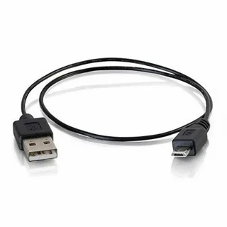
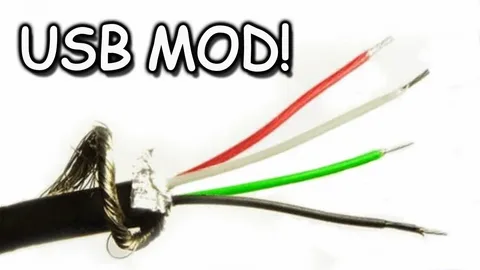
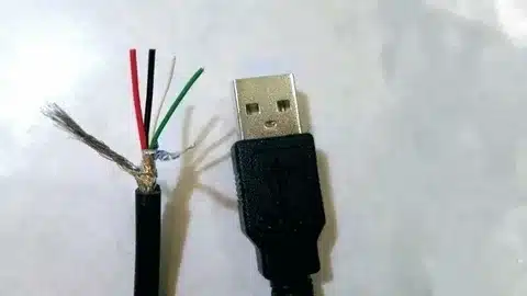
Standard USB-A to Micro/Mini USB (4 Wires)
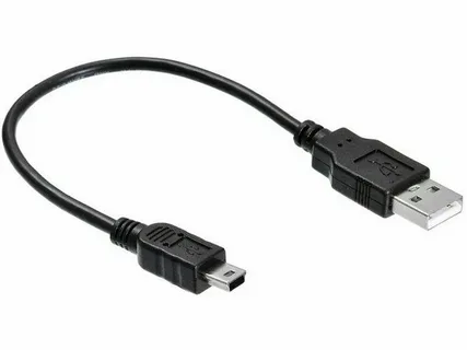
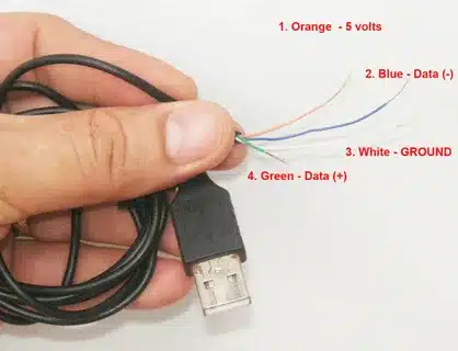
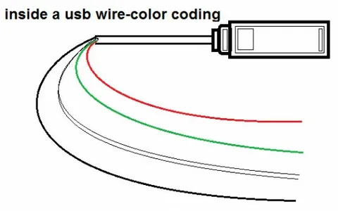
Most charging and data cables are four-wire, which can sometimes support low-speed connections :
- Red wire: +5V power (positive)
- Black wire: Ground (negative/return)
- White wire: Data- (D-)
- Green wire: Data+ (D+)
These four wires are the standard USB 2.0 configuration upon which most USB devices have rested in the past twenty years. The host, depending on the USB type, will supply the 5V DC power to the device via the power wires (red and black), but the data wires (white and green) will be a differential pair, connecting data in both directions.
The USB data transmission method of differential signaling has been chosen to reject common-mode noise and ensure high-quality transfer of data even in an electrically noisy environment. The data wires are twisted in pairs according to the USB pin-out to ensure suitable impedance and to alleviate electromagnetic interference.
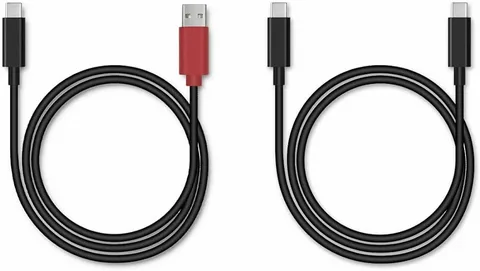
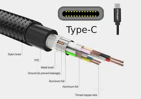
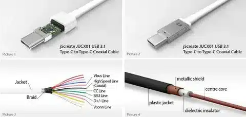
USB-C Cables (Variable Wire Count)
USB-C cables consist of 4 and 24 wires, respectively, along with microBb specifications.
Basic USB-C (4 wires):
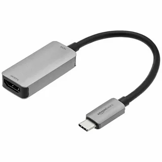
Mimicking the basic functionality of standard USB 2.0 cables, these bare-bones USB-C cables offer simple power and data transfer along with basic functionality.
Full-Featured USB-C (up to 24 wires):
- A number of higher-wattage power delivery lines.
- USB 3.0+ speeds: The high-speed data pairs of USB 3.0+.
- Device negotiation configuration channel wires.
- Signal integrity shield and ground contacts.
- Alternate mode pins (Sideband Use).
Full-featured USB-C cables are complex because of their flexibility in supporting a variety of protocols such as DisplayPort, Thunderbolt, and other power delivery specifications.
Power-Only USB Cables (2 Wires)
Some cables that are solely charging devices are:
- Red wire: +5V power
- Black wire: Ground
They are simple and generally stronger forms of cables that do not carry any data. These reduced-cable types, often using a B connector, find many applications in which data transfer is not necessary, including wall chargers, power banks, and decorative lighting applications.
Power-only cables can be made with a heavier gauge of wire, including the red wire, to be able to carry higher current, and are better suited to fast-charging applications where data capability would be an unnecessary overhead.
Understanding Wire Gauges and Current Capacity

The thickness of the wire (wire gauge) has a direct influence on the nature of the current-carrying capacity and the voltage drop of USB cables. Data lines are usually 28 AWG (American Wire Gauge), while the power lines, including the black wire, are usually 24-20 AWG. Smaller AWG wires are capable of conducting higher current per voltage drop.
In high-power applications such as charging a laptop with USB-C, the cables can be made with 16 AWG or even heavier power conductors. This interpretation of these specifications aids in the selection of cables suitable for various power needs from the power source, and explains why certain cables are faster in charging devices than others.
Step-by-Step Wire Identification Guide
Step 1: Prepare Your Workspace
Clean up a well-lit exposure space with everything in place. Also, when soldering, make sure there is good ventilation. Keep your tools where they are readily available and make sure that you have sufficient lighting to identify wire colours.
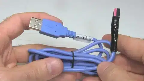
Step 2: Strip the Outer Jacket Carefully
At the end, cut the outer insulation 2 inches. Remove the jacket without stabbing the internal wires. Proper wire strippers of the correct gauge to prevent destruction of internal conductors, particularly for mini and micro connectors, should be used.
Step 3: Identify Wire Colors
Exposed color-coded wire records. Red, black and white, and green are common colors used, but there are other possible combinations by other manufacturers. A few of the manufacturers might employ alternative color schemes for corresponding wires and therefore, one should never assume anything by merely looking at the color.
Step 4: Test with Multimeter
Before making any changes, you must verify the wires that have power run on them:
- Set the multimeter to DC voltage
- Attach power to the connector
- Compare 2 wires to identify +5V and ground.
- Verify line continuity of data where appropriate.
Step 5: Strip Individual Wires
You need to remove about 1/4 inch of insulation on the wires you are using. Do not nick the conductor strands, as it will provide weak areas that could break under strain.
Advanced Wire Identification Techniques
In addition to simple color coding, there are at least a few techniques employed by professional technicians to designate wire functions. Multimeter continuity testing can be used to trace connector pin connections to wire ends. By analyzing the pattern of data lines, signal injection and oscilloscope analysis can be used to identify data lines.
In the case of complex cables containing several wires, it is useful to draw a pin-out diagram to keep track of the connections and to avoid making mistakes when making changes. This is particularly essential when dealing with USB-C cables that could contain more than one similar-colored wire of a different functionality.
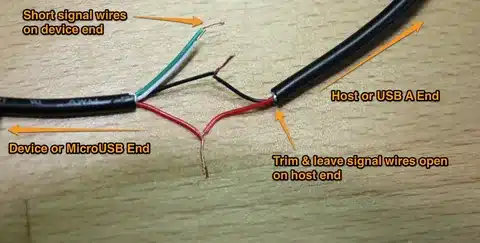
Power-Only Modifications: Safe Practices
In designing custom power cables, you can only think about the power wires:
For Charging Applications:
- Never connect data wires
- Always ensure that polarity is checked with a multimeter before connecting.
- Check the voltage level before connecting to equipment.
- Install the right gauge wire depending on current needs.
The simplicity of this methodology decreases complexity and weaknesses in a process, and it offers better consistency in delivering power to use in charging mechanisms.
Connection Methods and Their Applications
Temporary Connections:
- Twist and tape: Fast and not stable enough to use permanently.
- Wire nuts: Improved on a temporary basis.
- Breadboard connections: Perfect to prototype with.
Permanent Connections:
- Soldering: Best when it is to be permanent.
- Crimp connections: Crimp connections are Good in the field.
- Screw terminals: Can be used in panel mount services.
Some of the connection methods have particular applications that they are best suited to, and selecting the appropriate method will depend on the circumstances, such as permanence requirements, environmental requirements, and the tools available to choose.
Soldering Techniques for USB Cables
Correct practice in soldering is also essential in making good USB cable alterations. Most USB cable work requires a temperature-controlled soldering iron with a setting of about 350degC (662degF). Clean the tip frequently and solder with rosin-core and suitable flux.
When soldering USB cables, take care to move fast to prevent heat from damaging the other wires nearby. Heat the two surfaces before joining together and apply heat shrink tubing right after soldering to help relieve strain and provide insulation. During handling, make sure to put some rest before stressing the joints.
Heat Shrink Application Best Practices
Heat-shrink tubing is used to insulate and offer strain relief to modified cables. Most USB applications should use tubing with a 2:1 or 3:1 shrink ratio. The tubing must be made to fit over the connection with ease and then tightened when heated.

Heat uniformly with a heat gun or cautiously with a lighter, and rotate the connection so that it shrinks evenly. It should not be overheated, as that will harm the tubing or conductors under it. Household heat shrink when used properly should not have any gaps or loose spots.
Common Issues and Solutions
Why Won’t My Device Charge?
- Check continuity: Continuity of the wire by use of a multimeter.
- Inspect connections: Check corroded or loose connections.
- Verify voltage: Check that there is 5V at the other end of the device.
- Check current capacity: Check the required current in the wire gauge supports.
Cable Stopped Working After Modification?
- Internal wire break: This can be mostly caused by over-bending.
- Cross-connected signals: Power-connected data wires.
- Voltage drop: Gauge of wire insufficient to carry power.
- Poor insulation: Causes shorts between conductors.
Device Shows “Data Connection” Errors?
Certified cables should be used in high-power applications that have specific protocols for Power Delivery. Keep things simple: only use power-only connections with red and black wires, and ensure you identify the ID pin for proper functionality when charging.
Troubleshooting with Test Equipment
USB cable troubleshooting requires a good multimeter. Turn it to continuity mode to test for conductor breaks, and DC voltage mode to test power connections. With an oscilloscope, it is possible to detect problems with data signals, but this degree of testing is generally not accessible to simple adjustments.
To be more serious, in case of production or critical applications, it is recommended to invest in some specialized USB cable testers, which are capable of testing all functions such as data integrity, power delivery capability, and connector pin assignments.
Creative Applications for Custom USB Wiring
LED Strip Projects:
Use a caliper to cut USB power cables to the precise lengths required to install LED strips. This reduces the amount of unused cable length and provides neater installations in small areas such as computer cases or display cabinets.
DIY Charging Stations:
Design dedicated charging points with custom-length cables that can eliminate cable messes. Several USB power cords can run to one management system to create clean and professional-appearing results.
Portable Power Solutions:
Custom enclosures or installations can be powered by modified USB cables. Think of applications such as remote sensors, security cameras, or embedded systems.
Workshop Projects:
USB power is best used to test electronic components on the bench, as well as to energize development boards. Preparea special test lead with matching connectors to suit the normal project needs.
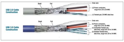
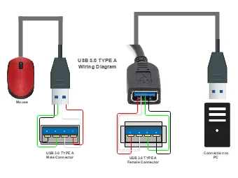
USB 3.0 and Higher Configurations
USB 3.0 cables contain more wires than the four standard wires:
- 4 regular wires (power and USB 2.0 data)
- Extra SuperSpeed datapairs (shielded).
- Additional ground and shield connections.
- EMITA drain wires.
These extra conductors allow the increased data rates of USB 3.0 without breaking backward compatibility with USB 2.0 devices. Spares The shielded pairs play an important role in supporting signal integrity at SuperSpeed frequencies.
USB Power Delivery (PD) Fundamentals
USB Power Delivery is an important development in USB capability, with power levels in the latest specifications reaching 240 W. This necessitates special cables with:
- Further high-voltage power conductors.
- Device negotiation (Configuration Channel (CC)) wires.
- Improved power integrity protection.
- Certified high current connectors.
USB PD is essential in the context of modern applications and particularly charging a laptop and supporting high-power devices.
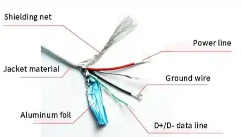
Electromagnetic Interference Considerations
USB cables are both potential sources and potential victims of electromagnetic interference (EMI). In high-electric-noise environments, it is important to ensure that the shielding and grounding are done correctly to provide reliable operation. There is the chance that modified cables have changed their original EMI properties, which can lead to interference.
Take into account the conditions under which modified cables will be deployed, and use suitable shielding. This can involve ferrite cores, extra shielding, or running the routing cables not next to the sources of interference.
Cable Length Limitations and Signal Integrity
USB standards have recommended data rates and power requirements as well as maximum cable length. USB 2.0 has a typical maximum length (5 meters), and high-speed USB 3.0+ has a maximum length of 3 meters or less (without active repeaters).
Signal integrity decreases with length because of the effects of resistance, capacitance, and inductance. Active USB extension solutions or other connection options should be considered when using long-distance applications that might be needed when building custom applications.
Testing and Verification Procedures
Always test modified cables before use:
Basic Tests:
- Check power wire voltage (must be 5V +-5%)
- Check continuity on connections.
- ensure there are no shorts between pairs of wires.
- Test with low-power device first.
Advanced Tests:
- Analysis of signal quality oscilloscope.
- EMI compliance testing
- Temperature rise under load
- Mechanical stress testing
Signs of Problems:
- Voltage below 5V means there is a problem with resistance.
- Heating devices while charging is an indicator of loose connections.
- The intermittent operation indicates loose connections.
- Signal integrity problems are shown by data errors.
Quality Assurance for Modified Cables
Introduce quality control measures involving any modified cables, in particular, for critical applications. Test results, document alterations, and operating parameters. Standardize common modification procedures so as to guarantee uniformity and precision.
After modifying cables, consider using a regular re-testing schedule because over time, connections suffer because of thermal cycling, mechanical stress, and oxidation.
Maintenance and Longevity Tips
Proper Installation:
- Glue all connections with suitable heat-shrink tubing.
- Sharp bends around blocking locations should be avoided.
- Use connection points for strain relief.
- Have spare cables in case of an emergency.
Regular Maintenance:
- Periodically check connections to ensure there is no wear.
- Continuity and test voltage on important cables.
- Cables with evidence of degradation shall be replaced.
- Always have spare parts to make quick repairs.
When to Replace:
- Outer insulation is visibly damaged.
- Occasional loss of connection.
- Slow charging performance
- The presence of heat or discoloration of any kind.
- Continuity or voltage test failure.
Environmental Considerations
Altered USB cables can be rated differently from the original manufactured cables. When creating modifications in the particular applications, also consider factors such as temperature range, humidity, and vibration, as well as chemical exposure.
There are other forms of protection that may be applied to industrial applications, like armored cable jackets, closed connections, or conformal coating on exposed conductors. Adjustments to the plans depending on the envisaged operating environment.
Frequently Asked Questions
Can I extend a USB cable using solder?
Yes, but mainly in power applications. Spliced data connections are subject to impedance discontinuities, which can result in data transmission issues. To use data applications, you should use appropriate USB extension cables or active repeaters.
Why do some cables charge faster than others?
Wire gauge depicts power delivery capacity. Smaller gauge wires will safely carry larger currents without undue voltage drop. Also, the charger and the device should be capable of high-current charging.
Should I modify branded cables?
Make changes with cheap, generic cables. Branded cables can typically lose warranties when modified and are, in general, too costly to use experimentally. Generic cables offer the same simple functionality at a cheaper price.
Can I create a USB cable that delivers more than 5V?
Standard USB operates at 5V. USB Power Delivery (PD) protocols and certified cables are needed at the higher voltages. To be on the safe side and to avoid compatibility problems, commercial high-power cables should be used, and DIY modifications should be left to learning and non-critical applications.
How do I identify USB-C pin assignments?
USB-C connectors contain 24 pins whose assignments are complex, depending on the type of cable and features required. Work with official USB-C specifications and pinout diagrams instead of trial and error. USB-C cable modifications are done by professionals with the help of specific knowledge and equipment.
What’s the difference between USB 2.0 and USB 3.0 cables?
USB 3.0 uses extra shielded pairs in addition to the four traditional conductors in order to achieve SuperSpeed data transfer without reducing the compatibility with older devices. The extra wires allow data rates to be as high as 5 Gbps compared to the 480 Mbps maximum of USB 2.0.
Conclusion
The knowledge of USB cable wiring gives possibilities to develop own solutions and solve common issues related to the USB interface. This information is priceless not only when you require certain lengths of cables to use on certain projects, but also when you need to know why certain cables work better than others.
Safety should always be a consideration in any modification work. Apply a cable of commercial manufacture to high-stakes applications, especially for small devices, and apply DIY skills to learning projects and non-critical applications. It is best to start with basic power-only changes to gain confidence and make more advanced changes as your abilities grow.
USB technology is an ever-changing world with new standards and capabilities being introduced every day. Knowing the basics discussed in this guide is a good starting point when dealing with the existing and upcoming USB implementations.
What do you do next with your USB cable? It can be their own-designed charging solutions, problem-solving around connection issues, or understanding the opportunities of USB power delivery, but the underlying principles and methods discussed here will ensure effective and safe outcomes. It is important to remember that practice and experience are your best teachers, and as your confidence and skills increase, you should start with simple projects and build up to more complicated applications.